How to install an automatic bollard
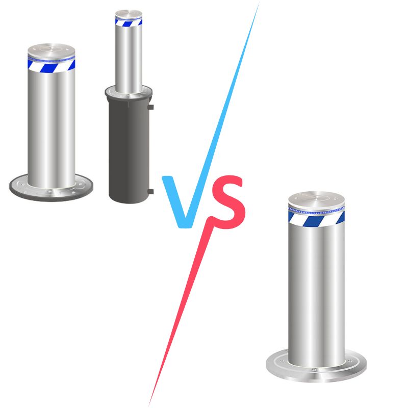
This article mainly introduces the installation of automatic bollards. Also known as automatic rising bollards, these devices effectively manage vehicle access to secure traffic order and the safety of key facilities and areas. After years of development, automatic bollards can be categorized into fully automatic, semi-automatic, removable, and fixed types.
Their protective capabilities meet the needs of civilian security and are suitable for high-traffic areas such as campuses, scenic spots, stations, high-speed railway stations, government buildings, hospitals, shopping malls, pedestrian streets, and other important locations.
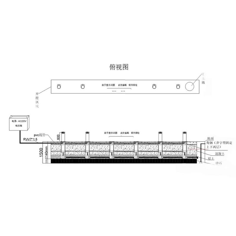
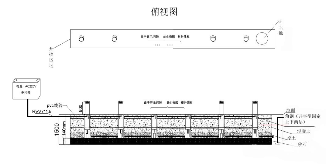
Installation Diagram
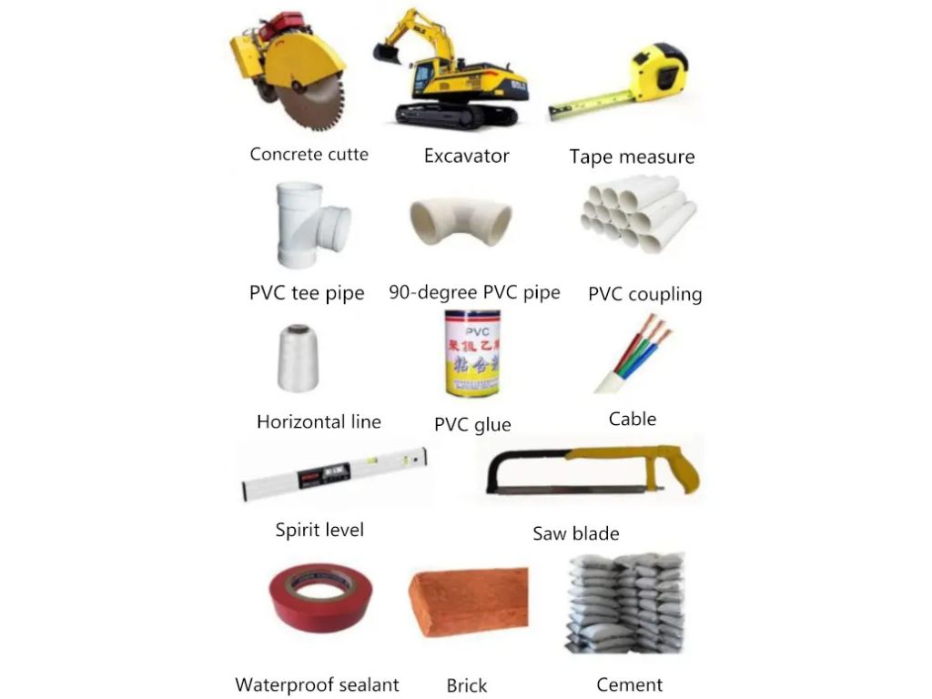
Preparation of Materials and Equipment Before Installation
-
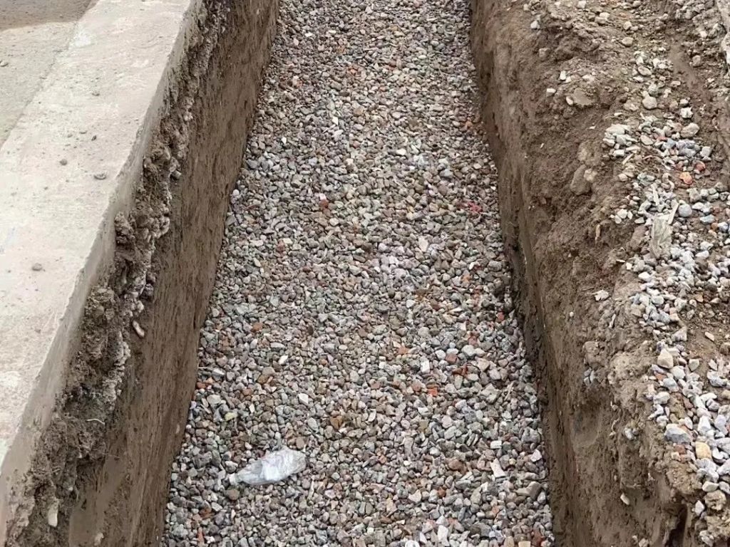
Gravel: A 20 cm layer of 3-5 cm diameter gravel should be placed at the bottom of the foundation trench for drainage.
-
Sand: A 20 cm thick sand layer should be placed above the gravel for drainage. The quantity of gravel and sand depends on the trench length, which is calculated by multiplying the trench's width (1 meter) by the total center-to-center distance of the bollards plus 1 meter, or based on the actual construction length on-site.
-
Steel Reinforcement: Use 1.4mm diameter threaded steel bars to reinforce the pre-buried bollard casing. A total of six steel bars should be placed according to the trench length.
-
Concrete: Concrete should be calculated based on the foundation trench's area and height (90 cm), while the amount of cement or asphalt required for surface restoration should be calculated on-site.
-
Polyethylene Pipes: Prepare a pipe from each bollard to the control box. The pipe should be reserved for each bollard.
-
Cables: Cables should be provided for connecting the control box to each bollard. Each bollard requires one cable. Grounding cables (BVR4㎡) are also needed.
-
Electrical Tapes: Electrical plastic tape, high-voltage waterproof tape, and asphalt tape should be prepared in accordance with the number of devices.
-
Tools and Equipment: Welding equipment, road surface cutting tools, electric hammers, excavation machines for the foundation trench, and other necessary tools for electrical and civil work.
-
Ensure No Obstacles: Before installation, ensure that there are no pipelines, cables, or other obstacles that might interfere with the construction, in accordance with local facility construction standards.
Construction Standards for Bollard Installation
Excavation of the Foundation Trench
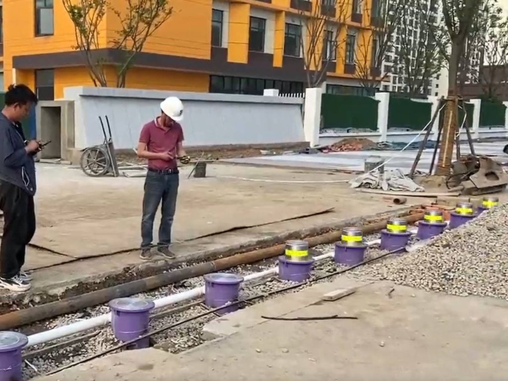
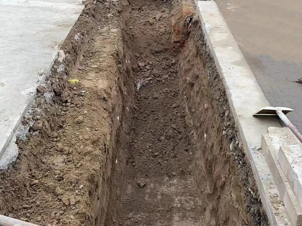
The foundation trench should have a depth of 1.5 meters, a width of 1 meter, and a length equal to the total center-to-center distance of all bollards, plus an additional meter.
Construction of a Water Retention Pit at Road Intersection
A water retention pit with a 600 mm corrugated pipe, 1.8 meters deep, should be installed. Inside the pit, an automatic pump with a float switch should be used for water drainage.
Removal of Road Surface
For cement, asphalt, or other hard road surfaces, first use a saw to cut along the edges of the foundation trench. Then use electric hammers or other tools to remove the surface layer, preparing the area for the restoration of the road surface.
Foundation Trench Requirements and Drainage Layer Setup
The foundation trench should have vertical walls and a smooth, level base. After excavation, fill the bottom with 3-5 cm gravel to create a drainage layer, 20 cm thick. Then, add a 20 cm layer of fine sand, ensuring uniform thickness across all layers to prepare for placing the pre-buried bollard casing.
Bollard Installation Steps
Installation of Pre-buried Components
-
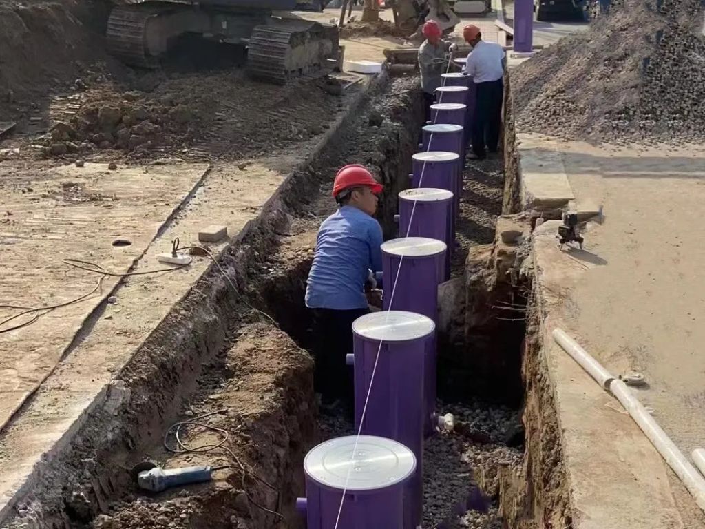
Install a Level Line for Bollard Installation: Ensure that the level lines at both ends are fixed tightly with steel nails to avoid displacement.
-
Backfill and Clean the Foundation Trench: Ensure that the height of each bollard’s pre-buried casing is consistent.
-
Install the Ultra-flat Base: Position the ultra-flat base centrally and vertically using reference lines. Tap it down with a hammer and adjust with a spirit level.
-
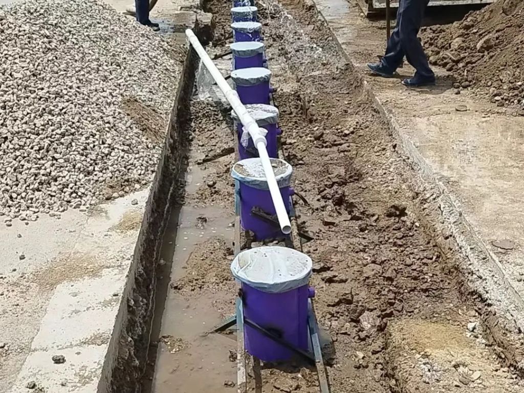
Install and Fix Pre-buried Casing: Ensure the pre-buried casing is aligned with the centerline, welding it temporarily to prevent movement during subsequent steps.
Laying Conduit and Wiring
-
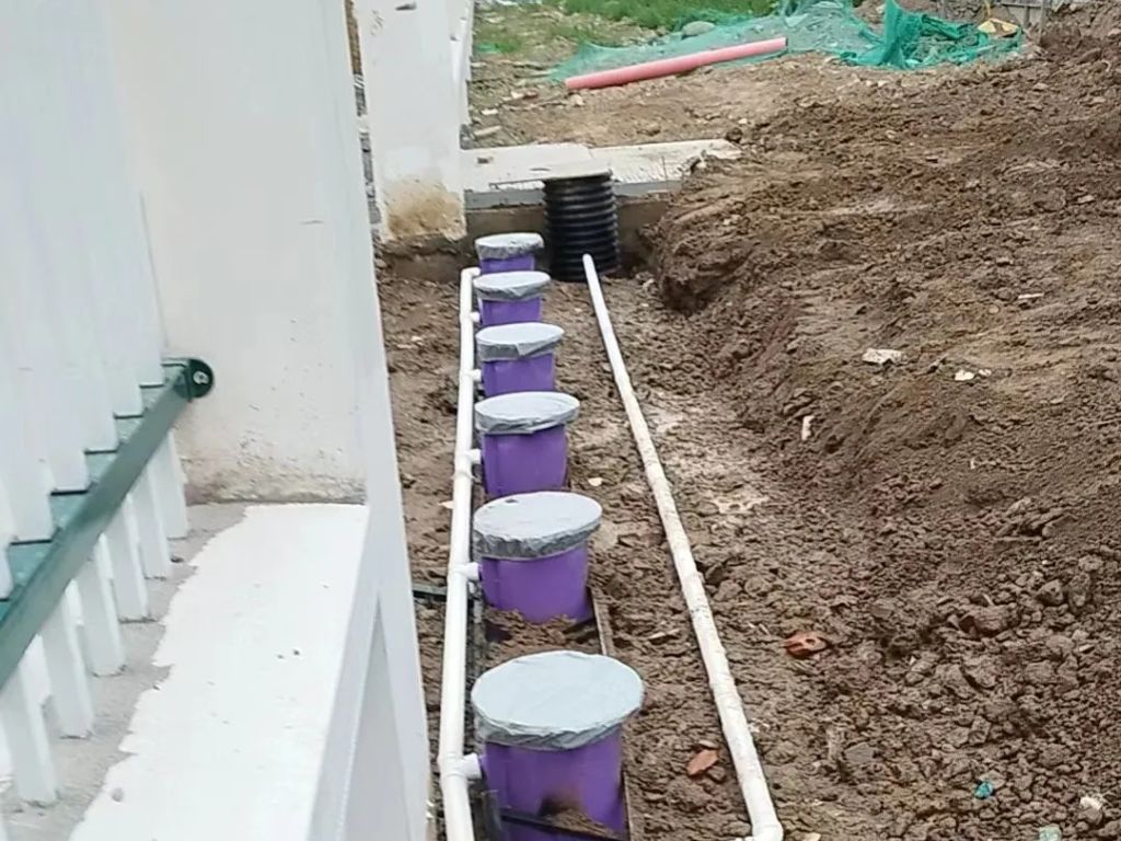
Install the Conduit for Wiring: Each pre-buried casing should have a drainage pipe at the bottom and a power conduit at the top. Insert a 1-inch conduit into the pre-buried casing and secure it with waterproof tape. Ensure that one end reaches the control box.
-
Wiring and Grounding: Each bollard requires a separate cable to the control box. The grounding cable should be welded to a copper bar inside the casing. Ensure proper connections to the control box and the grounding system.
-
Control Box Power Wiring: A 3*4.0㎡ cable should be run from the control box to the power distribution box, and separate conduit should be prepared for this.
Reinforcing the Pre-buried Casing with Steel Bars
-
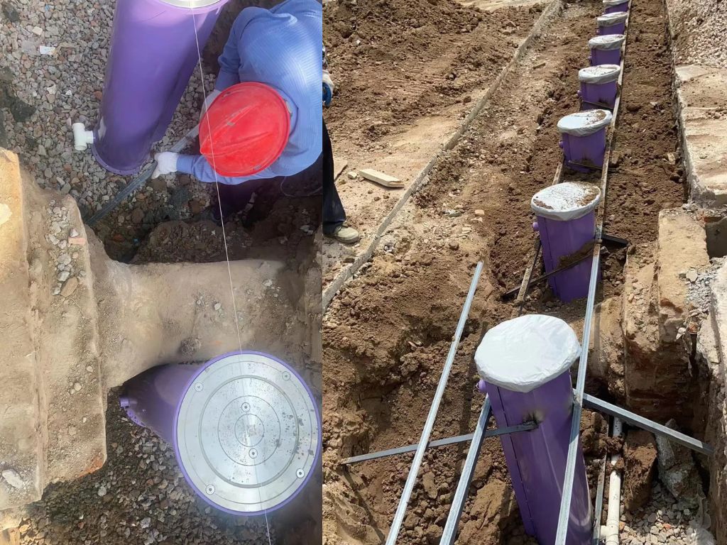
First Layer: Create a grid-shaped reinforcing structure using steel bars welded around the pre-buried casing. Ensure the bars are firmly inserted into the foundation trench, with the first layer 30 cm from the bottom of the casing.
-
Second and Third Layers: Continue reinforcing in the same manner, with the second layer at the middle of the casing and the third layer 20 cm below the top.
Wiring Process
-
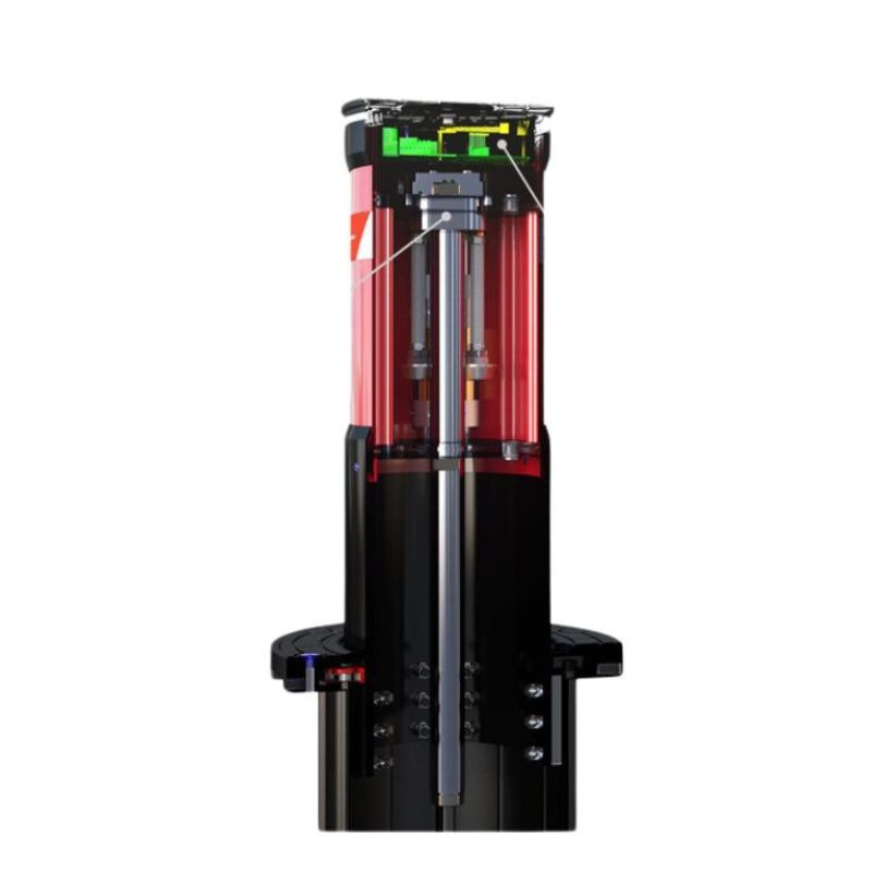
Power Unit Cable: The power unit’s motor requires a three-wire cable: red, black, and yellow. The electromagnetic valve uses two black wires. Some systems include a two-core wire for the warning light.
-
Wiring Procedure: Ensure that the motor wires, battery valve wires, and warning light wires are connected correctly, following the proper connections to the control box.
Backfilling and Concrete Pouring
Once the reinforcement is securely welded, and the grounding is completed, backfill with 20 cm of soil, compacting it to prevent concrete from seeping into the drainage layer. Pour concrete to a height of 10 cm below the road surface to leave space for restoring the original surface.
Device Debugging
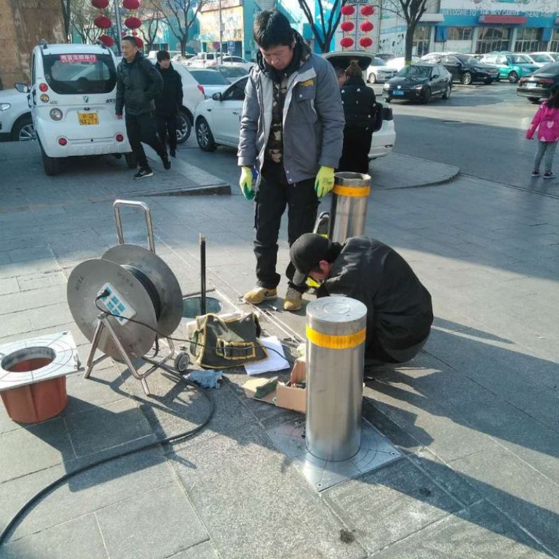
After the installation, adjust the guiding rods to ensure the bollard’s alignment with the surface panel, checking that the bollard rises and falls smoothly without any stalling.
Road Surface Restoration and Site Cleaning
When restoring the original road surface, ensure that it is level with the device’s upper panel. After completing the surface restoration, place barriers and signs. Wait until the concrete on the road and underground has fully set before using the device. Note: Avoid allowing heavy vehicles to pass for 7 days after the installation.
